Author: Hanksec Technical Team
High Temperature Label Materials | Polyimide PCB Label | PCB & Electronics | Failure Diagnosis & Process Validation
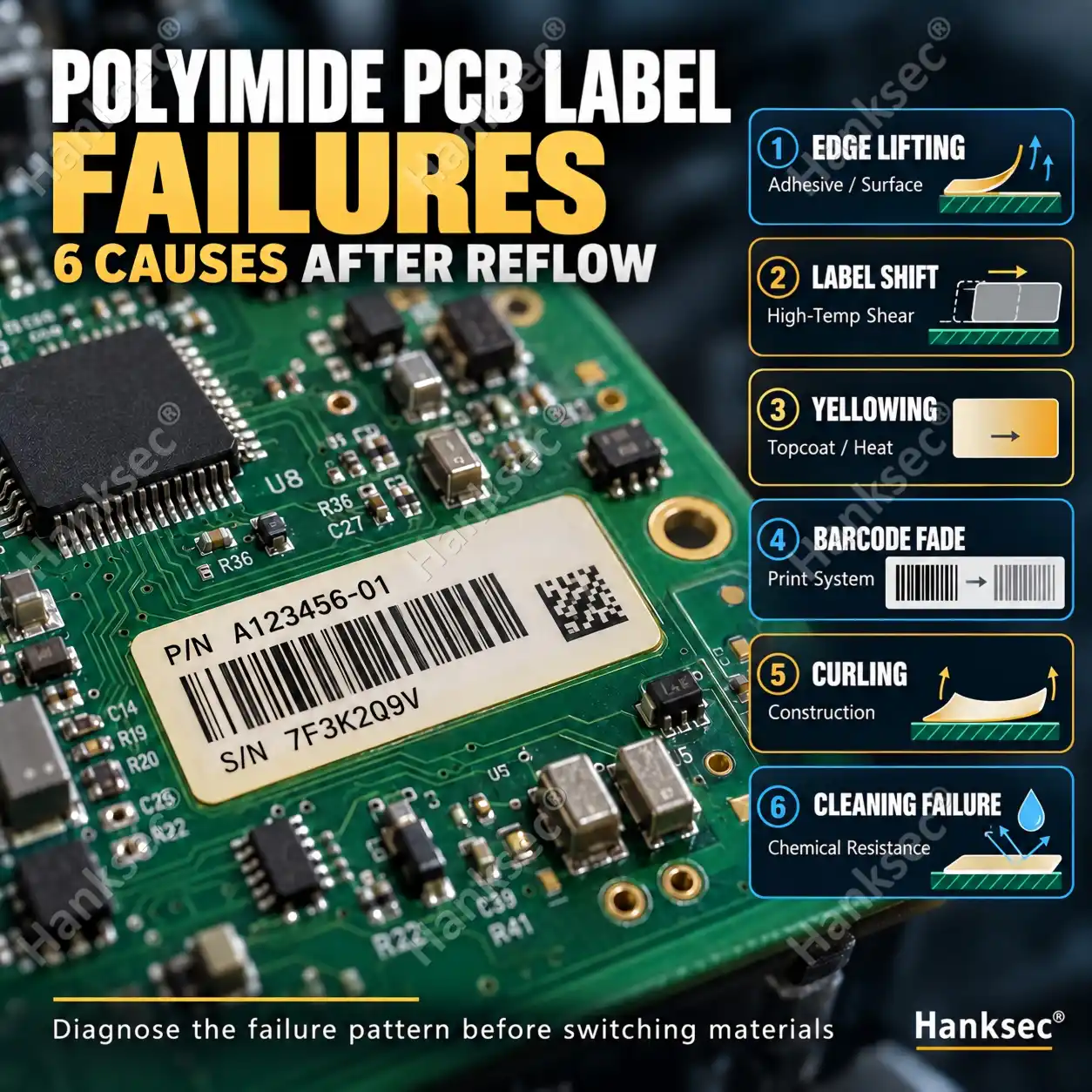
Quick Answer: If a polyimide PCB label lifts, shifts, yellows, curls or loses barcode readability after reflow or wave soldering, the polyimide film itself may not be the problem. Failures can come from the pressure-sensitive adhesive, printable topcoat, ribbon, PCB surface condition, cleaning chemistry or the complete thermal profile. Diagnose the failure pattern first before simply switching to a material with a higher temperature rating.
If your main question is how to interpret 260°C, 280°C and 300°C polyimide temperature ratings, see the Hanksec High-Temperature Polyimide Label Materials Guide. This article focuses instead on what to check when a polyimide PCB label fails during or after the actual production process.
What Failure Pattern Do You See After Reflow or Wave Soldering?
Before changing the label material, first document what failed, where it failed and when the failure appeared.
Different symptoms usually point to different parts of the label system.
| What You See | Possible Failure Area | Check First |
|---|---|---|
| Edges lift after reflow | Adhesive / PCB interface | Surface contamination, application pressure, dwell time, adhesive and heat profile |
| Label shifts during heating | High-temperature adhesive shear | Adhesive softening, peak temperature, exposure time and application timing |
| White surface yellows | Printable topcoat | Actual thermal profile, topcoat specification and repeated heat exposure |
| Barcode fades or scans inconsistently | Topcoat / ribbon / print system | Ribbon compatibility, print settings, heat exposure and cleaning chemistry |
| Label curls or changes dimensions | Facestock / complete construction | PI construction, coating balance, label geometry and thermal cycle |
| Passes soldering but fails during cleaning | Chemical resistance | Cleaning chemistry, print system, adhesive and exposed label edges |
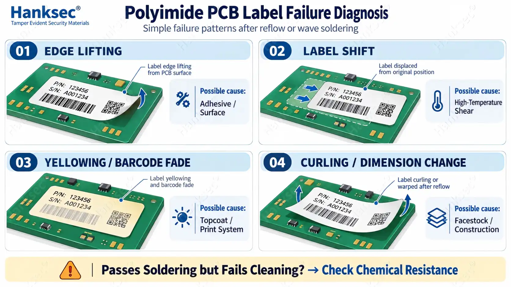
The important point is that “the label failed” is not a complete diagnosis. Edge lifting, label movement and barcode fading may all occur after the same reflow process but can have completely different causes.
Where Can a Polyimide PCB Label Fail?
A polyimide PCB label is a system. The PI film is only one part of that system.
A label can therefore fail even when the polyimide facestock itself remains visually intact.
| Part of the System | What It Must Do | Possible Failure |
|---|---|---|
| Printable Topcoat + Print | Keep barcode, QR code and variable information readable after heat and cleaning. | Yellowing, fading, smearing or poor barcode readability. |
| Polyimide Facestock | Maintain useful dimensional and physical stability through the process. | Curling, shrinkage or dimensional change. |
| Pressure-Sensitive Adhesive | Maintain sufficient bond and shear strength as the temperature changes. | Edge lifting, label movement, adhesive flow or loss of bond. |
| PCB Surface / Interface | Provide a clean and compatible surface for sufficient adhesive contact. | Localized lifting, weak bonding or inconsistent adhesion between boards. |
The PI film may survive while the complete label system fails.
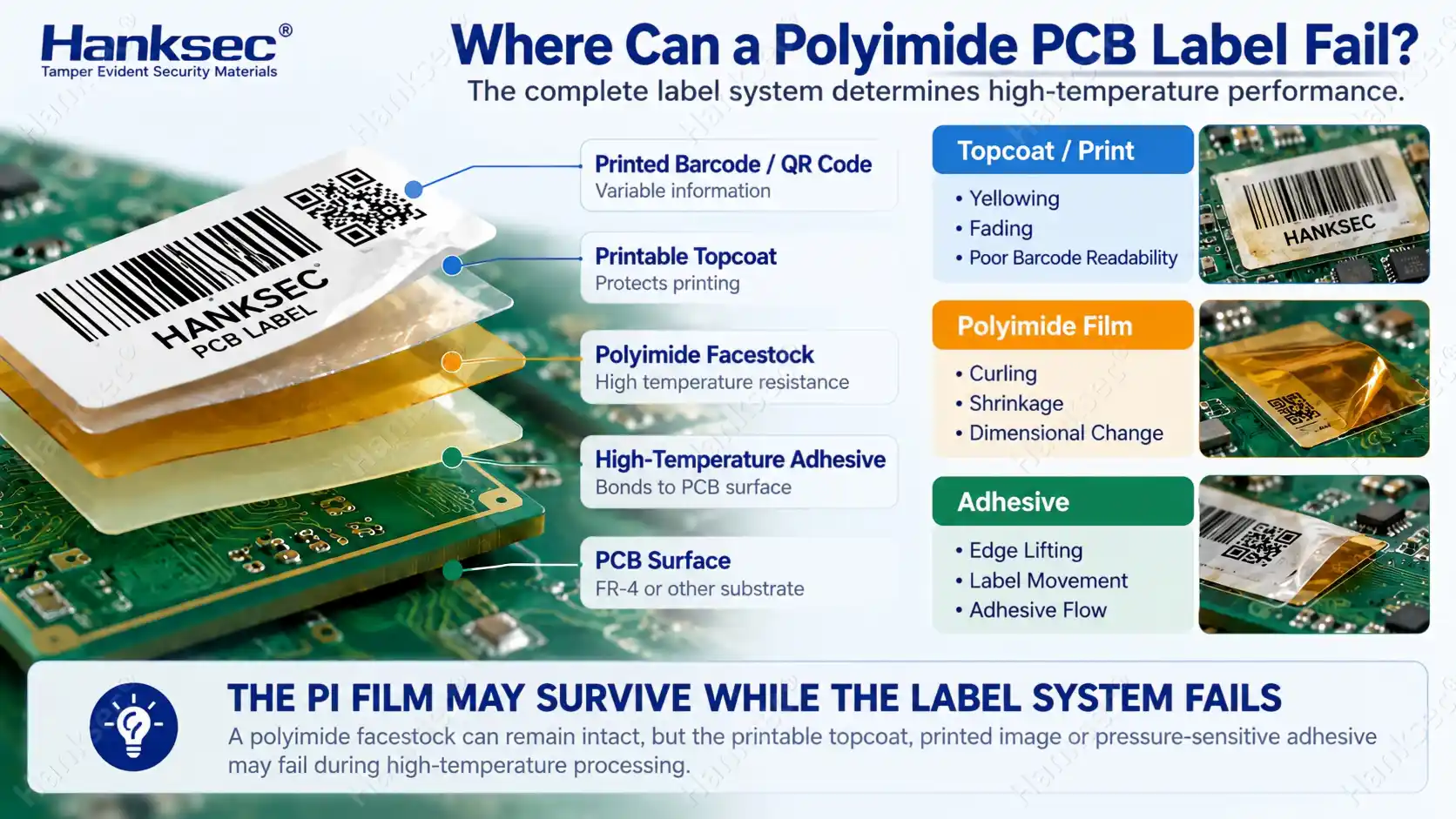
This is why changing only the PI film grade may not solve an application problem. The failure could be occurring above the film in the printable surface, below the film in the adhesive, or at the adhesive-to-PCB interface.
Why a Higher Temperature Rating Does Not Automatically Solve a Polyimide PCB Label Failure
Temperature rating still matters, but it should not be used as the only troubleshooting tool.
A polyimide label construction published for exposure reaching 300°C under specified conditions can still show edge lifting if the adhesive does not bond well to the actual PCB surface. It can still lose barcode readability if the print system is unsuitable. It can also pass soldering but fail later during PCB cleaning.
Published temperature values also describe different test conditions. Terms such as short-term heat resistance, defined-time exposure, peak temperature and service temperature should not automatically be treated as equivalent.
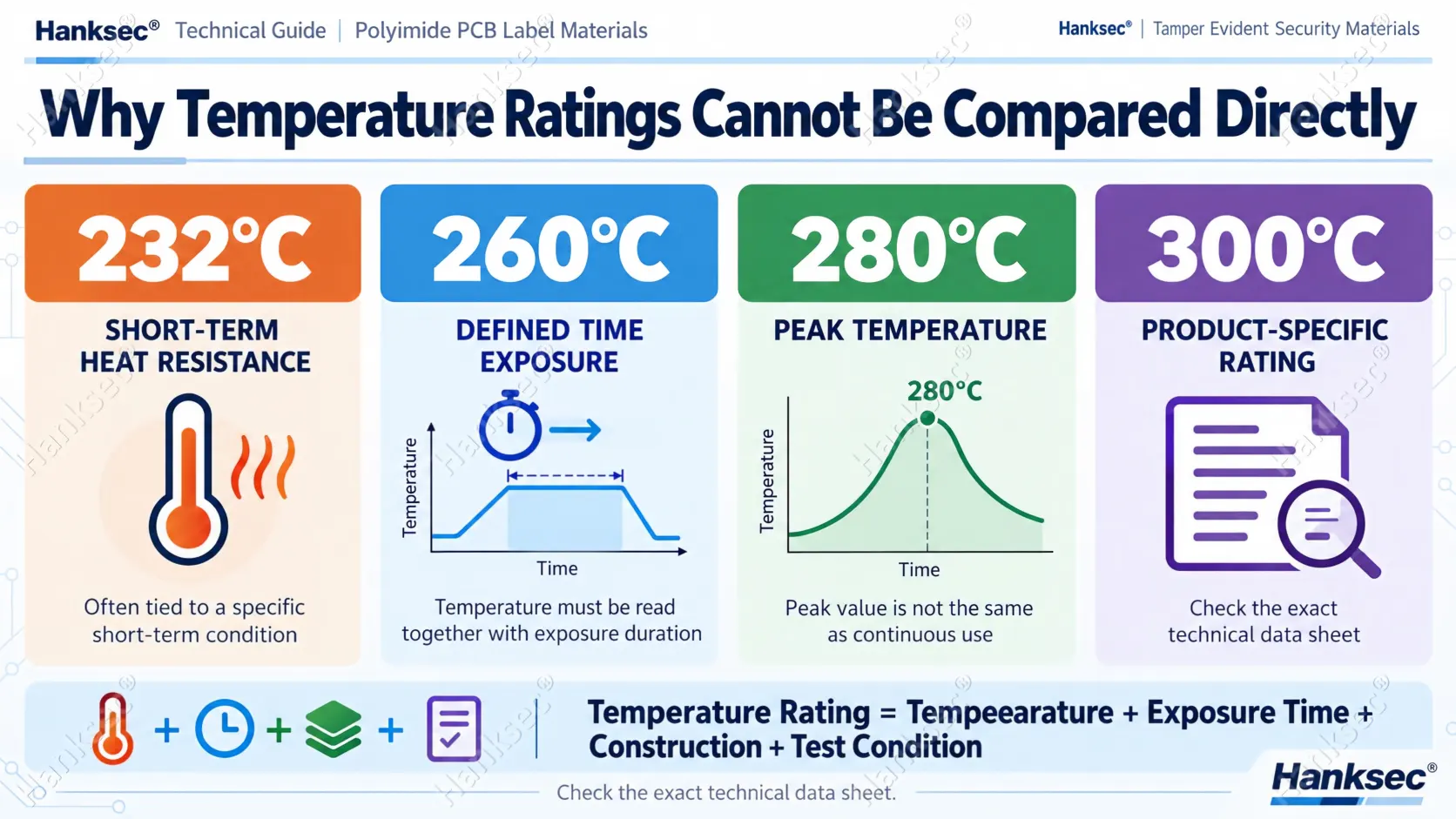
For example, commercial polyimide constructions from 3M, Avery Dennison and Brady use different terminology and test conditions when describing high-temperature performance.
If you need a detailed explanation of 260°C, 280°C and 300°C ratings, read the High-Temperature Polyimide Label Materials Guide. For failure analysis, the more useful question is:
What actually changed after the production process?
What Usually Causes Polyimide PCB Label Failures?
1. PCB Surface Contamination or Inconsistent Surface Condition
A high-temperature adhesive still needs sufficient contact with the real application surface.
Dust, oil, flux residue, silicone contamination or other surface residues can reduce effective adhesive contact. This can create apparently random edge lifting, especially when some boards pass and others fail under the same thermal profile.
If the failure begins only at one edge or one corner while the rest of the label remains flat, inspect the PCB surface and application process before assuming that the polyimide film is under-specified.
2. Insufficient Application Pressure or Dwell Before Heating
Pressure-sensitive adhesives develop bond through contact and wet-out. A label applied immediately before entering a thermal process may behave differently from a label that has had more time to establish contact with the substrate.
When troubleshooting, record:
- how the label is applied;
- application pressure;
- time between application and heating;
- PCB surface condition;
- and whether failure occurs consistently across all boards.
Changing the material without controlling these variables can hide the real cause.
3. Adhesive Softening or Loss of Shear During Heating
If the complete label moves or slides during heating rather than simply lifting at one edge, high-temperature adhesive shear should be investigated.
The polyimide film may remain flat while the adhesive becomes less resistant to movement at elevated temperature.
Check the actual peak temperature, time near peak, number of thermal cycles and whether the label is exposed to mechanical stress while the adhesive is hot.
4. Topcoat or Ribbon Is Not Stable Through the Full Process
A PCB label can remain perfectly attached and still fail its traceability function.
If a barcode becomes lighter, blurred or difficult to scan after soldering, inspect the complete printing system:
- printable topcoat;
- thermal-transfer ribbon;
- printer heat settings;
- print speed;
- thermal exposure;
- and cleaning chemistry.
Physical adhesion is not the same as traceability performance.
A label that remains on the PCB but produces an unreadable barcode should still be considered a failed identification system.
5. Thermal Stress Causes Curling or Dimensional Change
Curling, wrinkling or dimensional change can indicate that the complete construction is reacting to the thermal cycle.
The possible variables include the polyimide grade, coating system, adhesive layer, finished label geometry and the heating/cooling profile.
This type of failure should be separated from ordinary edge lifting. Edge lifting often points first to the adhesive interface, while curling can indicate a broader construction or dimensional-stability issue.
6. The Label Passes Soldering but Fails During PCB Cleaning
Soldering is not always the final challenge.
A label may survive reflow or wave soldering and then show print degradation, edge lifting or surface change during the cleaning stage.
For example, Brady’s B-724 technical data describes the material for multiple harsh-condition PCB wash cycles while also noting that degradation of the topcoat may occur with certain aqueous cleaning chemistries. This illustrates why heat resistance and cleaning resistance should be verified as separate parts of the complete process.
This is why qualification should follow the real process sequence:
Print → Apply → Reflow / Wave Solder → Clean → Inspect → Scan
Do not approve a material immediately after the heat cycle if the real PCB production process continues through chemical cleaning.
25 μm vs 50 μm Polyimide: Can Thickness Affect the Failure?
Yes, but not simply because one thickness has a higher temperature rating.
For otherwise comparable constructions, approximately 25 μm and 50 μm polyimide facestocks can behave differently in handling and converting because the thicker facestock is generally stiffer.
Thickness can influence:
- conformability to the application surface;
- small-label handling;
- die-cutting behavior;
- matrix stripping;
- automatic dispensing;
- and how easily the finished label bends with the application surface.
A 50 μm facestock therefore does not automatically solve edge lifting, curling or other thermal-process failures.
The adhesive and topcoat may also be different, and the two materials may have been designed for different process conditions.
For converters, thicker facestock can also change the converting window. The Hanksec High-Temperature Label Matrix Stripping case shows how facestock thickness, adhesive behavior, label dimensions, die cutting and waste-removal geometry can interact in production.
The useful question is:
Which complete construction solves the application problem without creating a new converting problem?
What Failure Information Should You Send the Supplier?
A message saying only:
“Our polyimide label failed after reflow. Please recommend a stronger material.”
usually does not provide enough information to identify the real cause.
For faster troubleshooting, send:
- Failure photo: clear close-up showing the exact failure pattern;
- When it failed: during heating, after cooling, during cleaning or during scanning;
- Peak temperature: highest actual process temperature;
- Exposure time: especially time near the peak temperature;
- Thermal cycles: single reflow, multiple reflow, wave soldering or rework;
- PCB surface: actual application surface and any known surface treatment;
- Label position: top or bottom side of the PCB where relevant;
- Finished label size: width, height and corner geometry;
- Printing system: printer, ribbon and barcode or QR requirements;
- Cleaning process: aqueous or solvent process where applicable;
- Material format: jumbo roll, slit roll or finished die-cut label.
If possible, also provide one unused label sample and one failed label sample from the production line.
Buyers sourcing roll material can review Hanksec High Temperature Polyimide Label Material when discussing alternative constructions for application trials.
How Should You Reproduce and Verify the Failure?
A useful troubleshooting test should reproduce the real production sequence instead of using only a generic oven test.
- Use the actual PCB surface. Do not qualify adhesion only on a convenient laboratory panel.
- Print the real barcode or QR code. Use the intended printer, ribbon and production settings.
- Apply the label consistently. Record surface preparation, pressure and dwell time.
- Run the actual reflow or wave-solder profile. Include repeated cycles if they occur in production.
- Continue through the real cleaning process. Do not stop the test immediately after soldering.
- Inspect the failure pattern. Check edge lifting, movement, curling, discoloration and adhesive flow.
- Scan the code again. Confirm barcode or QR readability after the full process.
- Change one major variable at a time. If comparing a new adhesive or construction, keep the other test conditions as consistent as practical so the real cause is easier to identify.
For converter-side qualification, printing, die cutting, liner release and matrix stripping should also be evaluated before approving bulk roll material. The Hanksec Security Label Material Quality Control Guide covers these broader material-control checks.
Frequently Asked Questions
Why does a polyimide PCB label lift after reflow?
Edge lifting can be caused by the adhesive-to-PCB interface, surface contamination, insufficient application pressure or dwell, adhesive behavior at elevated temperature, or the actual thermal profile. If the PI film remains flat and undamaged, check the adhesive and application surface first.
Why can a polyimide PCB label move during heating?
Label movement can indicate that the adhesive is losing sufficient shear resistance at elevated temperature. Peak temperature, exposure duration, dwell before heating and mechanical stress during the process should be reviewed.
Why does the barcode fade even when the label stays attached?
The adhesion system and printing system have different functions. The label may remain bonded while the printable topcoat, thermal-transfer ribbon or printed image loses contrast or durability after heat or cleaning.
Can a polyimide PCB label pass soldering but fail during PCB cleaning?
Yes. Heat resistance does not automatically guarantee compatibility with the downstream cleaning process. The adhesive, topcoat and printed image should be evaluated after the complete soldering and cleaning sequence.
Will changing from 25 μm to 50 μm polyimide solve edge lifting?
Not automatically. A thicker facestock changes stiffness and handling, but edge lifting is often controlled by the adhesive-to-substrate interface, application conditions and thermal process. Thickness should be selected as part of the complete construction rather than used as a standalone fix.
Need Help Diagnosing a Polyimide PCB Label Failure?
Hanksec® supplies high-temperature polyimide label materials for PCB, electronics and label-converting applications. Share the failure photo, PCB surface, peak temperature, exposure time, label size, printing method and cleaning process. Our technical team can help evaluate whether the failure is more likely related to the adhesive, printable surface, polyimide construction or process conditions.
REQUEST FAILURE ANALYSIS & MATERIAL TESTING →
Hanksec® | Polyimide PCB Label Materials · Failure Analysis · Jumbo Rolls · Slit Rolls · Custom Material Solutions